{{ title }}
★ REQUESTED BY MATHWORKS AS AN EXAMPLE OF STUDENT WORK
{{ category }}
Role: Electrical Lead · Team: 9 · Timeline: 3 months
Overview
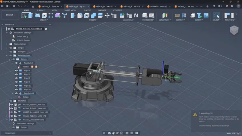
A mobile manipulator, nicknamed Christopher, with five degrees of freedom: a three-joint revolute–prismatic–revolute arm on a two-wheel differential drive base. It searches for an AprilTag worn on a person’s ankle, drives up to it, rotates to square itself with the leg, then extends and clamps. Perception, state estimation, planning, and control run on a Raspberry Pi with a Simulink model deployed to it.
My Role
- Owned the PCB board and the basic arm kinematics on a nine-person team.
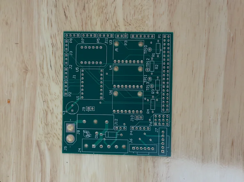
- Created schematics for the board, did the layout, ran DRC, and ordered it from JLC PCB.
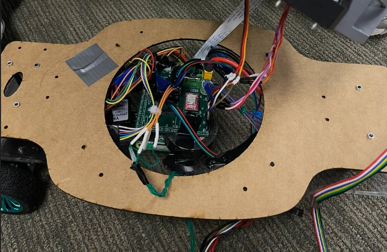
- Once it arrived (late, because the first package got stolen), did the entire electrical integration for the robot in two days (IR sensors, stepper motor, servos, DC motors). Besides having to fly-wire a fix for one of the wheel DC motors due to an unnoticed net issue in Altium, the PCB board worked seamlessly and Christopher had his full intended range of motion.
- Created a Python script for the Raspberry Pi that allowed real-time keyboard control of all of the motors, which I passed onto the Simulink software team to accelerate their process.
Tools & Tech
Arm Kinematics
To reach its moving targets, the arm needed wheels. Because PID only runs once the robot is parked, a rotational joint lets it square up to the ankle without needing to park at a precise angle, and a prismatic joint then extends forward — the robot parks far enough back that it can’t bump into any legs before extending. The wrist is able to move to grab the ankle from different orientations, and the end effector closes around it to grab. Joint 1 spins the base 360°, joint 2 extends the arm along one line, joint 3 pitches the wrist to absorb variation in leg size and stance. Four Denavit–Hartenberg parameters per link reduce the whole arm to a table.
q = [θ₁ d₂ θ₃] · LIMITS: θ₁ ∈ [−π, π] · d₂ ∈ [0, 187.908] mm · θ₃ ∈ [−π, π] · mm
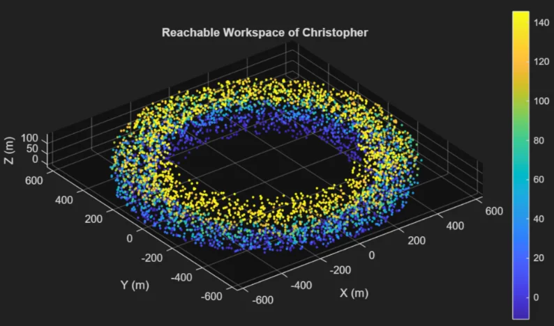
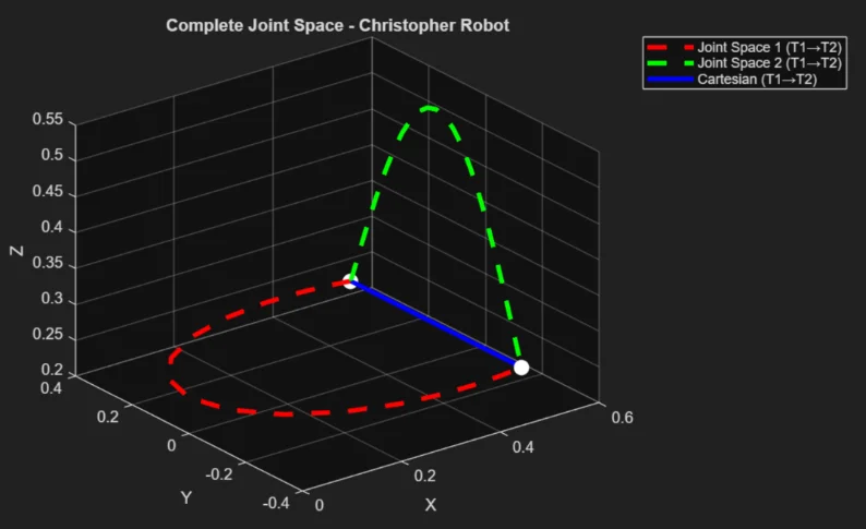
Using forward kinematics, via a MATLAB toolbox, we were then able to map the reachable workspace of Christopher. For the combined task-space trajectory and waypoint planning, 2 arbitrary waypoints (in the range of the figure) were chosen to demonstrate the entire trajectory of our robot, which is shown in the second figure.
System Overview
PCB Design Decisions
CLICK TO ZOOM
CLICK TO ZOOM
- Breakout Boards
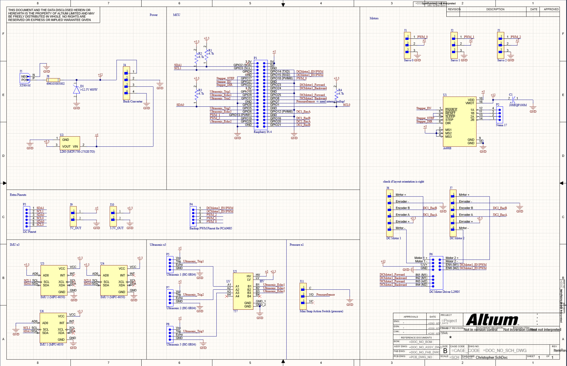
The goal for this PCB was to simplify the wiring process between breakout boards, motors, and voltage step downs. I chose to not order a PCBA with individual ICs and custom circuitry due to budget and a tight deadline, and therefore, I integrated familiar breakout boards for parts such as the IMUs, voltage converters, and drivers. - Circuit Protection
Placed a fuse holder immediately downstream of the power input for overcurrent protection; the swappable rating let me adjust the trip point during bringup. Added a TVS diode (12.5V standoff) to protect against inductive transients and to conduct on reverse polarity so that the fuse blows instead of frying the system. - 3 Power Rails
A minimum of 12V was needed to power the DC motors. Therefore, 12V was sourced from a LiPo battery, and was then stepped down via buck converter to 5V in order to power the servos. An LDO then took that down to 3.3V for the sensors. - Backups
Since the project was on a tight deadline, it was crucial that the board work on the first try, and also have backup options in case the PID needed additional sensors, or if it turned out that the sensors we had planned on didn't work. Therefore, I added an extra pinouts for the I2C busses, as well as the 5V and 3V rails, so that other sensors could be added to the system. I also added a separate pinout so that it would be possible to add a PWM pinout board to the system, since the Raspberry Pi did not have enough PWM pins, and we needed a backup in case our software PWM signals did not function correctly.
Results & Simulink
Control and kinematics were developed and validated in a MATLAB/Simulink plant model (motor dynamics, back-EMF, encoder ticks, differential drive) before touching hardware, comparing PID and LQR control against the same reference trajectories and checking forward/inverse kinematics against the toolbox solution. The Simulink model was then deployed onto the robot arm, tuned, and tested.
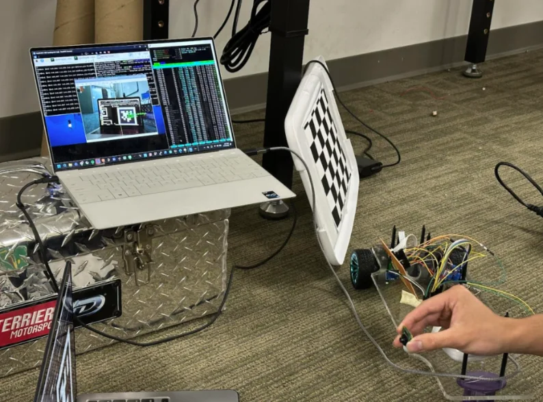
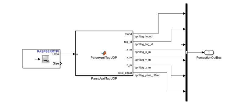
APRILTAG DETECTION TESTING
Full derivations, the DH parameters, controller tuning, and simulation results are documented in the final project report.
Back to All Projects