{{ title }}
{{ category }}
Role: Electrical Co-Lead / UI Lead / Pan and Tilt Lead · Team: 6 · Timeline: 8 months
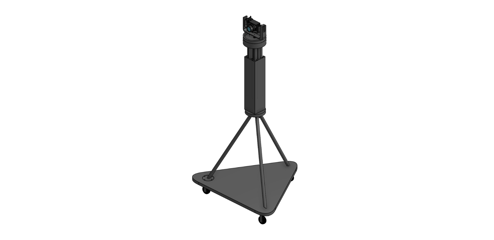
Overview
A motorized tripod that filmmakers can tilt, pan, move up and down, and dolly using a remote WiFi application. The TakeOne Tripod system allows the user to mount their own camera onto a tripod fixture and then use an application to remotely control the camera’s movements. Remotely controlled movements of the system include dollying (moving across the floor), moving the camera up and down, panning the camera horizontally, and tilting the camera while viewing a live footage stream of the view of the camera.
My Role
- Mechanical camera housing, tilting, and panning structure.
- Android application UI that communicates with the Raspberry Pi onboard the tripod, with pre-programmed and real-time motor control.
- Footage streaming pipeline from camera to Android App.
- Electrical Integration and Testing of the whole system, integrating height adjustment and dollying components together with my system and the microcontroller with the help of one other teammate.
Tools & Tech
Panning and Tilting Component
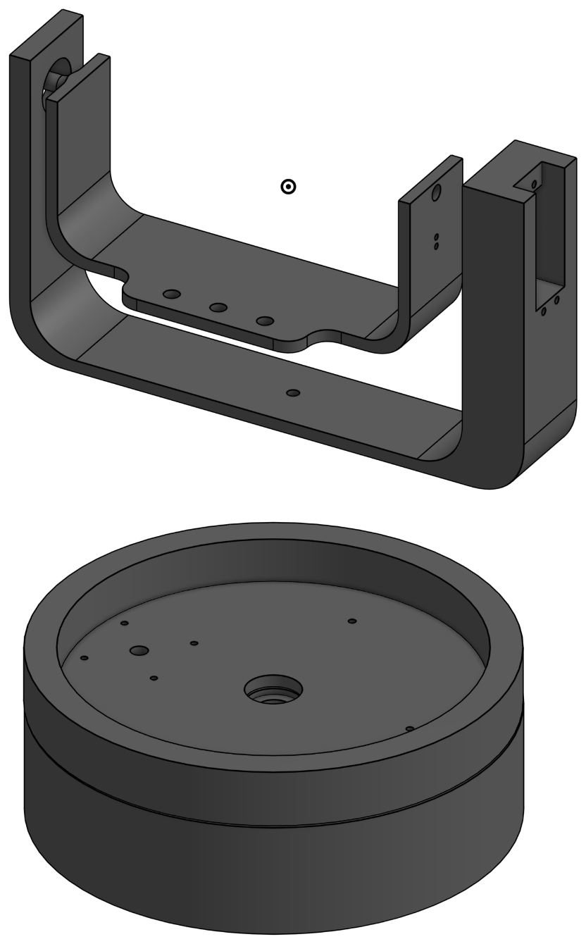
The panning and tilting component includes an inner cradle, which is used to attach the camera via a standard screw that is usually used for tripod mounting. The outer cradle then houses a servo motor, which tilts the inner cradle, accounting for the tilting motion of the camera. Finally, the bottom is responsible for the panning motion of the camera, and includes a stepper motor, a pulley system, and a rail for the tilting cradle to glide on for stability.
The initial design for the panning and tilting system was not structurally sound enough to hold a 1 kg camera (the inner cradle kept breaking) and the panning motion was not precise (it had no location feedback, and the servo would move more to one side than another with the same command) or stable (the tilting cradle would visibly tilt when the camera tilted due to only one point of contact with the panning motor).
To remedy these issues, I remade the inner and outer cradle print with filled edges for fewer breakage points and a higher infill. The panning motor was also swapped for a stepper motor, since there were no 360 servos with location feedback available for purchase, and a stepper motor allowed for precise movements due to the ability to count the steps. Panning motor housing was also created with a rail in order to stabilize the tilting cradle around the edges, and a pulley system with a large gear ratio was implemented to produce slower movement from the stepper motor without visible step movement in the footage. Finally, multiple holes in different places were created in the inner cradle to accommodate different camera models, and they were also moved further to one side of the inner cradle to move the center of gravity of the camera closer to the center of the structure to reduce strain on the motors.
The system is compatible with any camera that weighs below 1 kg, is 140 mm or less in width, and has a standard 1/4-20 UNC screw mount. The panning mechanism is then able to tilt the camera from −30° from the horizontal up to 90° from the horizontal at the speed indicated in the application. This allows the user to remotely perform shots that would otherwise require physical movement of the camera, including bird’s-eye views, low-angle/worm’s-eye views, tilt-up/tilt-down reveals, and pedestal-style transitions.
The panning mechanism is located below the tilting mechanism and can pan the user’s camera from side to side within a 360° range, at a speed that is set by the user in the application. This enables the user to remotely perform panning shots, tracking shots, sweeping establishing shots, 360° rotational shots, and slow panoramic timelapses.
Remote Control Application
The initial system used Bluetooth and was only able to remotely control the motors; however, without being able to see what the camera was seeing and being able to start and end the recording remotely, the benefits of the functionality of the tripod were lost, and, therefore, I decided to move the system to WiFi.
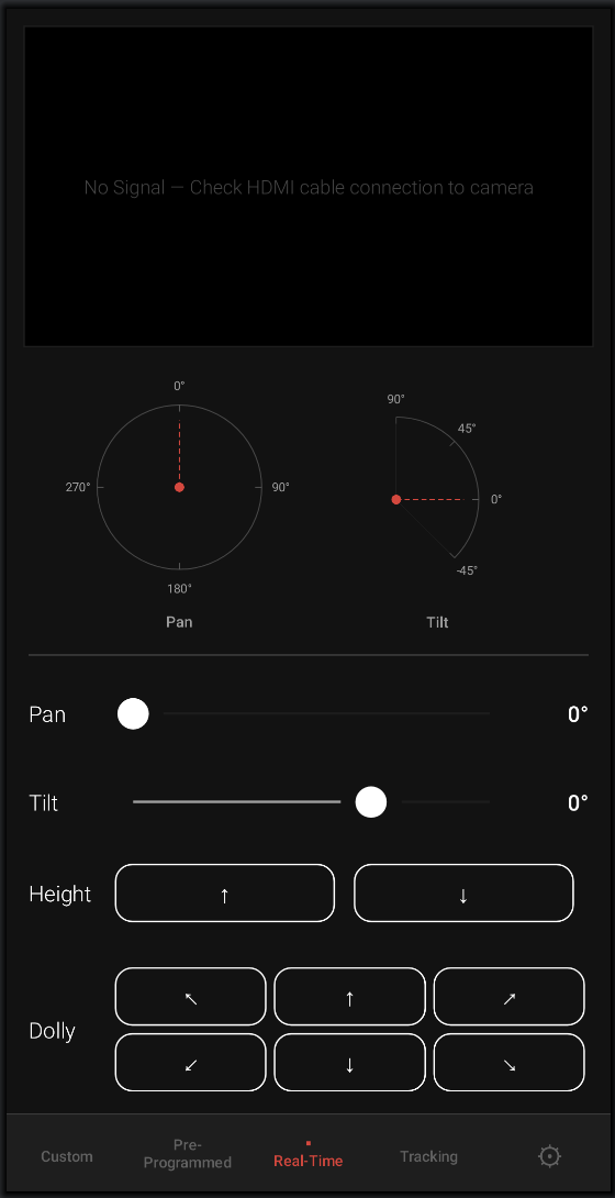
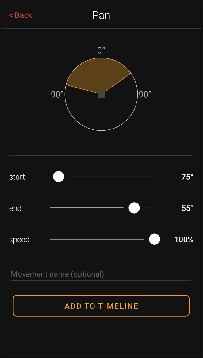
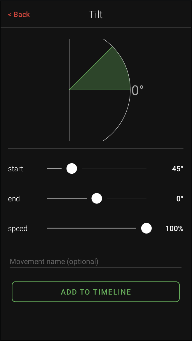
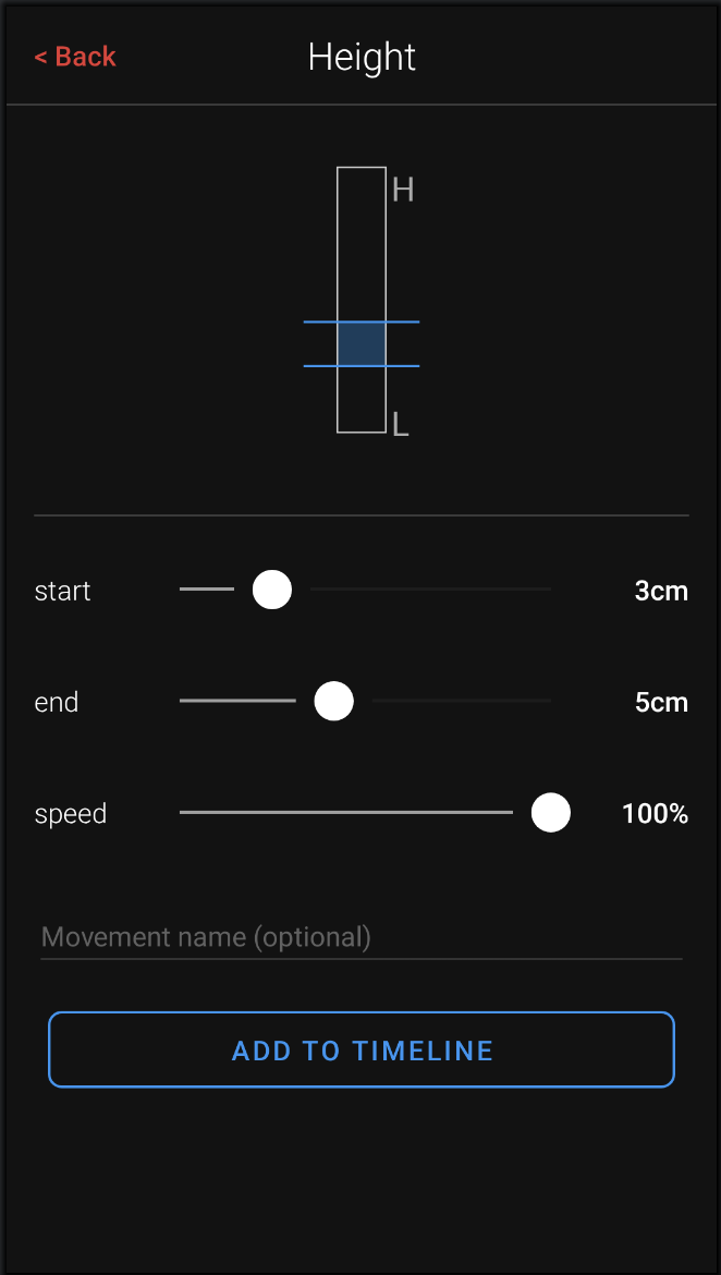
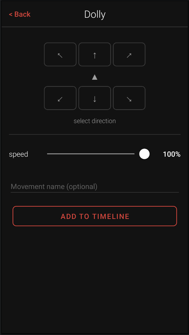
The final system uses an Android Studio Application, which accepts user commands to control the motors in real time or via pre-programmed sequences, through its user interface, which then relays these commands over WiFi to the Raspberry Pi. The application has real-time pan, tilt, height, and dollying control, as well as the option for users to set pre-programmed pan, tilt, and height adjustment movements. Furthermore, it has real-time camera footage displayed on screen so that the user can see where they are moving the camera.
The real-time control interface provides the user with control of the panning and tilting mechanisms via sliders that set the angular position of the camera. When the user moves their finger along the slider, the camera moves with the same speed. The application also incorporates visualizers for these movements to help orient the user. Similarly, the user is provided with up and down arrows to control the height of the camera. When pressed, the camera starts moving up or down. The user is also able to control the dollying movement and direction via an arrow interface. When the user presses on any given arrow, the entire tripod starts moving in that direction. Finally, the application is also capable of providing a live feed of the camera’s view if the user’s camera has an HDMI monitor output.
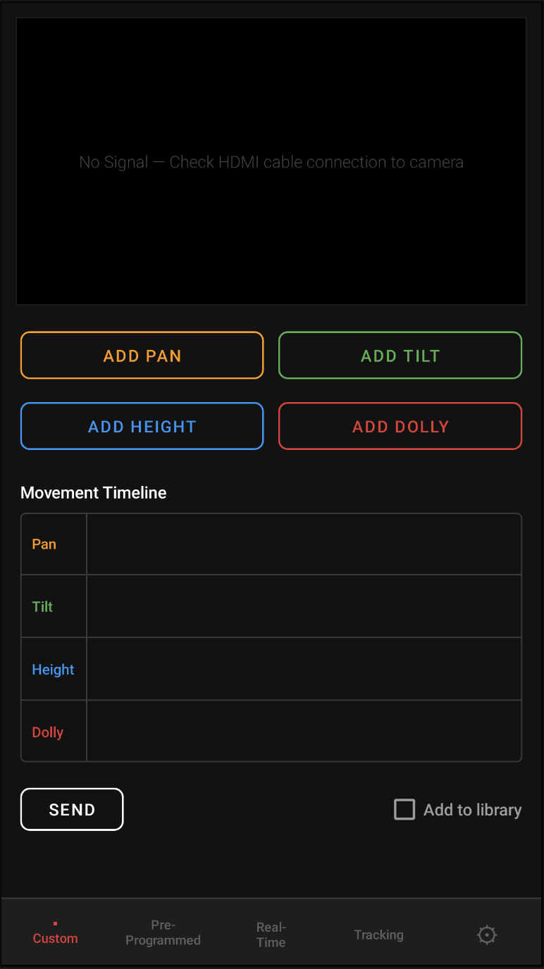
I also designed a custom control section that allows the user to control the tripod by choosing one of the 4 movements, setting its parameters, and then adding it to the timeline depending on when the user would like the movement performed in relation to the start of the sequence. After creating the movement timeline, you can press the send button for the tripod to start the custom sequence.
The footage streaming pipeline collects footage from the camera via HDMI cable to the capture card, to MicroUSB, to the Raspberry Pi, then streams the footage over WiFi TCP to the Android Studio application. TCP was chosen because it achieved faster results than UDP during testing, and TCP has packet arrival validation, which ensures that no parts of the video are lost.
Electrical Integration and Testing
Initially, the team worked in sub-teams: myself on panning and tilting, 2 members on height adjustment, and 3 members on dollying. In order to integrate this system we designed a system with 12 V and 5 V rails, with a buck converter as a stepdown. For protection, we added a fuse and used a battery with built-in battery management. Altogether, the final system included four 12 V DC motors, two servo motors, and one stepper motor, all of which were individually controlled by a library housed on the Pi, which activated upon receiving TCP signals from the application.
After wiring our system together, it worked on the first try, which is a testament to the benefits of thorough, initial power calculations and planning.
Results
By the end of the project, we integrated the system and had all required functionality (panning, tilting, height adjustment, and dollying with real-time and pre-programmed control). However, this movement was not smooth. This was because this turned out to be a heavily mechanical project and all of our team members were either electrical or computer engineers, and therefore the mechanical structure still needs improvement and the learning curve slowed us down. However, this lack of quality was also due to not having clearly defined objectives throughout the project for each team, and while some team members set deadlines for themselves, others did not. Realising this halfway through the project, I asked each subteam what still needed to get done and made a tight timeline that I shared with everyone, and asked people each week if they completed their tasks, which helped us get the giant scope of the project done on time, even though it could still use improvement.
Back to All Projects